Ducktop2 subsystem
Battery management & charging.
Ducktop2's three-cell battery board and charging circuit.
BMS routed · bench tests pending
View source on GitHub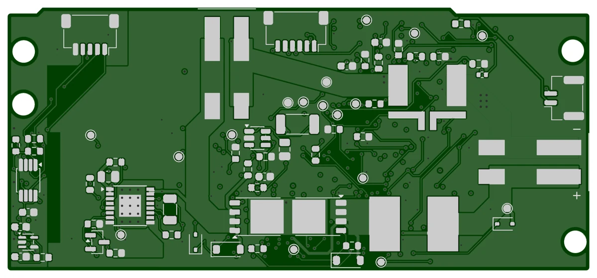
- Battery
- 3 cells in series
- BMS
- 4 layers
- Monitor
- BQ76922
- Charger
- ISL9241
The battery monitor and protection circuits are on their own board. The center board handles charging and system power. That keeps the cell connections and protection MOSFETs together on the BMS.
Cell monitoring and disconnects
The current BMS uses a TI BQ76922 to monitor the three-cell pack. High-side charge and discharge MOSFETs control the main current path. Cell-temperature inputs and a limited startup branch are part of the protection design.
Measuring current
A four-terminal 2 mΩ shunt provides separate force and sense connections. INA381 circuits provide independent charge and discharge current guards. The board targets 8 A discharge and up to 3 A charging; these are targets, not measured current ratings.
Charging
An ISL9241 charger on the center board supplies the pack and system power path. The BMS handles individual cell measurements and disconnects. Cell balancing is disabled in the initial prototype profile while the monitoring, temperature, and charging behavior are checked.
Checks before power-up
The BMS is routed, with no unconnected items or physical DRC findings. I still need to measure its voltage drop and temperature, test the protection circuits, and check the cells. The first assembly leaves the drive-release links out so I can program and test it before enabling the main power path.
Current status
The BMS is routed but still needs bench tests. I haven't verified its current capacity, fault response, or charging behavior on hardware. The charger circuit is saved on the center board, which is still being placed and routed.
Next steps
- Assemble the initial board in its disabled configuration.
- Calibrate current and cell measurements, then test faults and recovery.
- Test the cells, wiring, temperature rise, and connection to the charger.