Power electronics
BLDC motor controller.
A brushless motor controller built around an STM32G4.
PCB routed · not powered yet
View source on GitHub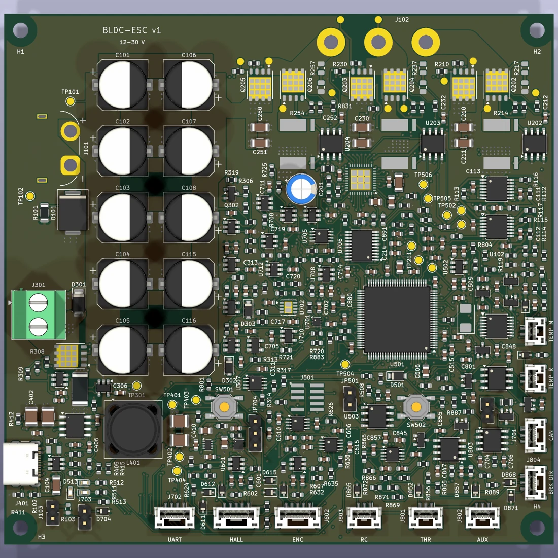
- Board
- 116 × 112 mm
- Copper
- 4 layers
- MCU
- STM32G474
- Gate driver
- DRV8353S
I'm building a reusable, open-source controller for BLDC and PMSM motors, similar to a small VESC. The first test motor is a 26 V Groschopp gearmotor. I plan to get Hall-based control working first, then look at FOC once the hardware is tested.
Three-phase power stage
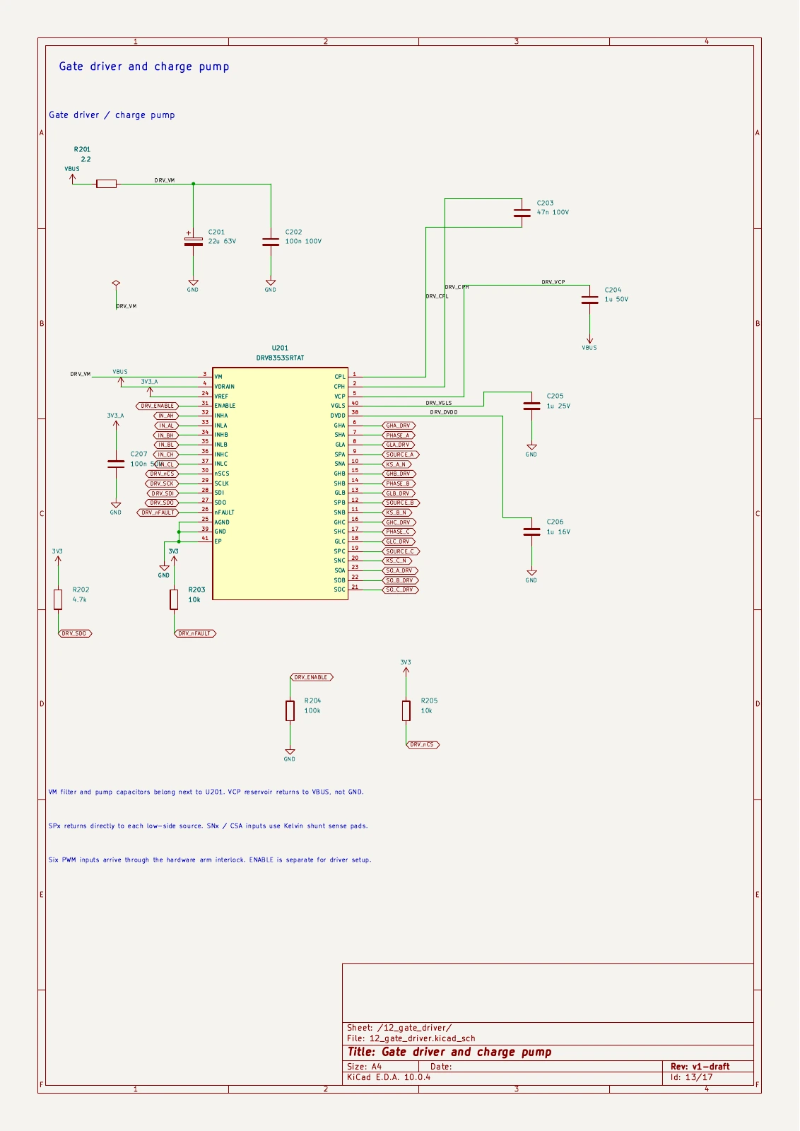
The circuit uses an STM32G474VET6 and a DRV8353S gate driver with six 60 V MOSFETs. It also has a brake chopper. Before ordering, I still need to confirm the PCB stack and cooling plan.
Current measurement and protection
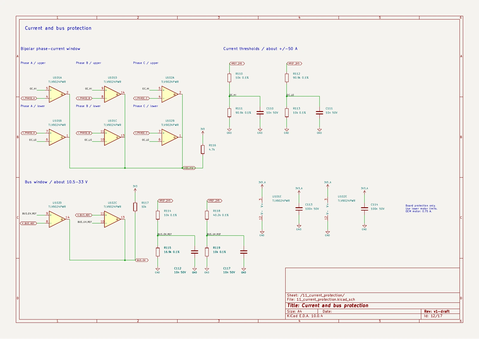
Three 1 mΩ phase-current shunts and INA241 sensing circuits feed the measurement path. Hardware overcurrent protection, a watchdog, voltage sensing, and temperature inputs are part of the design. Current ratings remain design targets until the assembled board has been tested.
Feedback and debugging
There are Hall and encoder inputs for motor feedback, plus SWD, USB-C, UART, and CAN FD connections. The starter firmware can report inputs and ADC readings over UART and read the gate driver's registers when the required checks pass.
Firmware so far
The starter firmware builds and passes its host tests, but I haven't flashed it to this board. It keeps the bridge and brake PWM outputs low. Commutation, FOC, USB, and CAN code are still to come. I haven't run a motor with it or implemented sensorless control.
Current status
The PCB is fully routed and the fabrication files are prepared. KiCad's saved design checks are clean. I haven't built or powered the board yet, and I still need to check the test motor's sensor pinout.
Next steps
- Confirm the fabrication stack, impedance, component availability, and cooling plan.
- Assemble the board and verify supplies, current readings, protection, and gate signals.
- Bring up Hall-based commutation on the test motor before attempting FOC or sensorless operation.
Schematics
All schematic sheetsThe gate driver and current-protection circuits are shown below. The full schematic also covers the power stage, MCU, sensors, and other protection circuits.